SLU
EAS-A193 Class Notes
|
SLU EAS-A193 Class Notes |
Faults and Faulting |
Rocks are very slowly, but continuously moving and changing shape. Under high temperature and pressure conditions common deep within Earth, rocks can bend and flow. In the cooler parts of Earth, rocks are colder and brittle and respond to large stresses by fracturing. Earthquakes are the agents of brittle rock failure.
A fault is a crack across which the rocks have been offset. They range in size from micrometers to thousands of kilometers in length and tens of kilometers in depth, but they are generally much thinner than they are long or deep. In addition to variation in size and orientation, different faults can accommodate different styles of rock deformation, such as compression and extension.
Not all faults intersect Earth's surface, and most earthquakes do no rupture the surface. When a fault does intersect the surface, objects may be offset or the ground may cracked, or raised, or lowered. We call a rupture of the surface by a fault a fault scarp and identifying scarps is an important task for assessing the seismic hazards in any region.
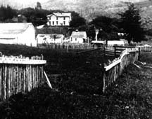
Fence offset about 11 feet during the 1906 San Francisco California Earthquake (Photo from the U.S. Geological Survey) |
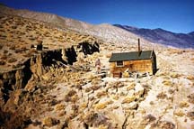
Fault scarp formed during the Decemeber 16, 1954 Dixie-Valley-Fairview Peaks, Nevada earthquakes (Photo from the Steinbrugge Collection, Earthquake Engineering Research Center, U.C. Berkley). |
When an earthquake occurs only a part of a fault is involved in the rupture. That area is usually outlined by the distribution of aftershocks in the sequence.
We call the "point" (or region) where an earthquake rupture initiates the hypocenter or focus. The point on Earth's surface directly above the hypocenter is called the epicenter. When we plot earthquake locations on a map, we usually center the symbol representing an event at the epicenter.
Generally, the area of the fault that ruptures increases with magnitude. Some estimates of rupture area are presented in the table below (The original data are from Wells and Coppersmith, Bulletin of the Seismological Society of America, 1994).
|
Date
|
Location
|
Length (km) | Depth (km) | (Mw) |
|---|---|---|---|---|
| 04/18/06 | San Francisco, CA |
|
|
|
| 07/21/52 | Kern County, CA |
|
|
|
| 12/16/54 | Fairview Peak, NV |
|
|
|
| 12/16/54 | Dixie Peak, NV |
|
|
|
| 06/28/66 | Parkfield, CA |
|
|
|
| 02/09/71 | San Fernando Valley, CA |
|
|
|
| 10/28/83 | Borah Peak, ID |
|
|
|
| 10/18/89 | Loma Prieta, CA |
|
|
|
| 06/28/92 | Landers, CA |
|
|
|
Although the exact area associated with a given size earthquake varies from place to place and event to event, we can make predictions for "typical" earthquakes based on the available observations.
| Magnitude |
Fault Dimensions (Length x Depth, in km)
|
|---|---|
|
|
1.2 x 1.2 |
|
|
3.3 x 3.3 |
|
|
10 x 10 |
|
|
16 x 16, 25 x 10 |
|
|
40 x 20, 50 x 15 |
|
|
140 x 15, 100 x 20, 72 x 30, 50 x 40, 45 x 45 |
|
|
300 x 20, 200 x 30, 150 x 40, 125 x 50 |
These numbers should give you a rough idea of the size of structure that we are talking about when we discuss earthquakes.
Although the number of observations of deep fault structure is small, the available exposed faults provide some information on the deep structure of a fault. A fault "zone" consists of several smaller regions defined by the style and amount of deformation within them.
|
|
|
The center of the fault is the most deformed and is where most of the offset or slip between the surrounding rock occurs. The region can be quite small, about as wide as a pencil is long, and it is identified by the finely ground rocks called cataclasite (we call the ground up material found closer to the surface, gouge). From all the slipping and grinding, the gouge is composed of very fine-grained material that resembles clay. Surrounding the central zone is a region several meters across that contains abundant fractures. Outside that region is another that contains distinguishable fractures, but much less dense than the preceding region. Last is the competent "host" rock that marks the end of the fault zone.
Active faults are structure along which we expect displacement to occur. By definition, since a shallow earthquake is a process that produces displacement across a fault, all shallow earthquakes occur on active faults.
Inactive faults are structures that we can identify, but which do no have earthquakes. As you can imagine, because of the complexity of earthquake activity, judging a fault to be inactive can be tricky, but often we can measure the last time substantial offset occurred across a fault. If a fault has been inactive for millions of years, it's certainly safe to call it inactive. However, some faults only have large earthquakes once in thousands of years, and we need to evaluate carefully their hazard potential.
Reactivated faults form when movement along formerly inactive faults can help to alleviate strain within the crust or upper mantle. Deformation in the New Madrid seismic zone in the central United States is a good example of fault reactivation. Structure formed about 500 Ma ago are responding to a new forces and relieving strain in the mid-continent.
Faulting is a complex process and the variety of faults that exists is large. We will consider a simplified but general fault classification based on the geometry of faulting, which we describe by specifying three angular measurements: dip, strike, and slip.
DipThe fault illustrated in the previous section was oriented vertically. In Earth, faults take on a range of orientations from vertical to horizontal. Dip is the angle that describes the steepness of the fault surface. This angle is measured from Earth's surface, or a plane parallel to Earth's surface. The dip of a horizontal fault is zero (usually specified in degrees: 0°), and the dip of a vertical fault is 90°. We use some old mining terms to label the rock "blocks" above and below a fault. If you were tunneling through a fault, the material beneath the fault would be by your feet, the other material would be hanging above you head. The material resting on the fault is called the hanging wall, the material beneath the fault is called the foot wall. |
 |
 |
StrikeThe strike is an angle used to specify the orientation of the fault and measured clockwise from north. For example, a strike of 0° or 180° indicates a fault that is oriented in a north-south direction, 90° or 270° indicates east-west oriented structure. To remove the ambiguity, we always specify the strike such that when you "look" in the strike direction, the fault dips to you right. Of course if the fault is perfectly vertical you have to describe the situation as a special case. If a fault curves, the strike varies along the fault, but this is seldom causes a communication problem if you are careful to specify the location (such as latitude and longitude) of the measurement. |
SlipDip and strike describe the orientation of the fault, we also have to describe the direction of motion across the fault. That is, which way did one side of the fault move with respect to the other. The parameter that describes this motion is called the slip. The slip has two components, a "magnitude" which tells us how far the rocks moved, and a direction (it's a vector). We usually specify the magnitude and direction separately. The magnitude of slip is simply how far the two sides of the fault moved relative to one another; it's a distance usually a few centimeters for small earthquakes and meters for large events. The direction of slip is measured on the fault surface, and like the strike and dip, it is specified as an angle. Specifically the slip direction is the direction that the hanging wall moved relative to the footwall. If the hanging wall moves to the right, the slip direction is 0°; if it moves up, the slip angle is 90°, if it moves to the left, the slip angle is 180°, and if it moves down, the slip angle is 270° or -90°.
|
 |
| Hanging wall movement determines the geometric classification of faulting. We distinguish between "dip-slip" and "strike-slip" hanging-wall movements.
Dip-slip movement occurs when the hanging wall moved predominantly up or down relative to the footwall. If the motion was down, the fault is called a normal fault, if the movement was up, the fault is called a reverse fault. Downward movement is "normal" because we normally would expect the hanging wall to slide downward along the foot wall because of the pull of gravity. Moving the hanging wall up an inclined fault requires work to overcome friction on the fault and the downward pull of gravity. When the hanging wall moves horizontally, it's a strike-slip earthquake. If the hanging wall moves to the left, the earthquake is called right-lateral, if it moves to the right, it's called a left-lateral fault. The way to keep these terms straight is to imagine that you are standing on one side of the fault and an earthquake occurs. If objects on the other side of the fault move to your left, it's a left-lateral fault, if they move to your right, it's a right-lateral fault. When the hanging wall motion is neither dominantly vertical nor horizontal, the motion is called oblique-slip. Although oblique faulting isn't unusual, it is less common than the normal, reverse, and strike-slip movement. |
|
Fault Styles
|
The style of faulting is an indicator of rock deformation and reflects the type of forces pushing or pulling on the region.
Near Earth's surface, the orientation of these forces are usually oriented such that one is vertical and the other two are horizontal. The precise direction of the horizontal forces varies from place to place as does the size of each force.
The style of faulting that is a reflection of the relative size of the different forces - in particular is the relative size of the vertical to the horizontal forces. There are three cases to consider, the vertical force can be the smallest, the largest, or the intermediate (neither smallest or largest). If the vertical force is the largest, we get normal faulting, if it is the smallest, we get reverse faulting. When the vertical force is the intermediate force, we get strike-slip faulting.
Normal faulting is indicative of a region that is stretching, and on the continents, normal faulting usually occurs in regions with relatively high elevation such as plateaus.
Reverse faulting reflects compressive forces squeezing a region and they are common in uplifting mountain ranges and along the coast of many regions bordering the Pacific Ocean. The largest earthquakes are generally low-angle (shallow dipping) reverse faults associated with "subduction" plate boundaries.
Strike-slip faulting indicates neither extension nor compression, but identifies regions where rocks are sliding past each other. The San Andreas fault system is a famous example of strike-slip deformation - part of coastal California is sliding to the northwest relative to the rest of North America - Los Angeles is slowly moving towards San Francisco.
As you might expect, the distribution of faulting styles is not random, but varies systematically across Earth and was one of the most important observations in constructing the plate tectonic model which explains so much of what we observe happening in the shallow part of Earth.
Fault Type:
Deformation Style:
Force Orientation:
We use a specific set of symbols to identify faulting geometry on maps. The symbols are called earthquake focal mechanisms or sometimes "seismic beach balls". A focal mechanism is a graphical summary the strike, dip, and slip directions.
An earthquake focal mechanism is a projection of the intersection of the fault surface and an imaginary lower hemisphere (we'll use the lower hemisphere, but we could also use the upper hemisphere), surrounding the center of the rupture.
|
| The intersection between the fault "plane" and the sphere is a curve. The focal mechanism shows the view of the hemisphere from directly above. We can show the orientation of a plane (i.e. the strike and dip) using just one curve, to include information on the slip, we use two planes and shade opposite quadrants of the hemisphere. |
The price we pay for the ability to represent slip is that you cannot identify which of the two planes on the focal mechanism is the fault without additional information (such as the location and trend of aftershocks).
Some example focal mechanisms are shown below.
You should memorize the top three, which correspond to dip-slip reverse and normal faulting on a fault dipping 45°, and strike-slip faulting on a vertical fault. The lower two mechanisms correspond to a low-angle reverse earthquake (the dip is low) and the last example is an oblique event with components of both strike-slip and dip-slip movement. The strike of any plane can be read from a focal mechanism by identifying the intersection of the fault (shown as the boundary between shaded and unshaded regions) with the circle surrounding the mechanism (and using the dip-to-the-right rule).
Stress is a force per unit area or a force that acts on a surface.
When I described the types of forces associated with the different styles of faulting (in the section "Faults and Faulting"), I was describing stresses (the force per unit area on the fault).
Friction is a stress which resists motion and acts in all natural systems.
For earthquake studies, friction on faults and the orientation and relative magnitudes of the "regional" stresses that determine the style of faulting are of primary interest and importance.
Strain is a measure of material deformation such as the amount of compression when you squeeze or the amount of elongation when you stretch something.
In elastic deformation the amount of elongation is linearly proportional to the applied stress, and an elastic material returns to its original shape after the stress is relieved. Additionally, a strained, elastic material stores the energy used to deform it, and that energy is recoverable.
As you know, some regions repeatedly experience earthquakes and this suggests that perhaps earthquakes are part of a cycle. The effects of repeated earthquakes were first noted late in the nineteenth century by American geologist G. K. Gilbert. Gilbert observed a fresh fault scarp following the 1872 Owens Valley, California earthquake and correlated the scarp and uplift from a single earthquake with the uplift of the Sierra Nevada mountains. Decades later, following the 1906 San Francisco, California earthquake, H. F. Reid presented a similar hypothesis to explain better-documented movements along coastal California measured both before and after a large earthquake. Reid's model of the earthquake cycle has become known as the "Elastic Rebound Model".
| The key to Reid's success was the availability of "before" and "after" observations for the earthquake which allowed him to see strain build in the crust before the event, and then see that strain release during the earthquake.
In the diagram, we have two blocks of rock separated by a fault. As the two blocks move in opposite directions, friction acting on the fault resists movement and keeps the two sides from sliding. The rock strains as elastic energy is added, eventually, the strain loads the fault too much and overcomes the frictional "strength" of the fault. The rocks on either side of the fault jerk past each other in an earthquake. The earthquake releases the stored elastic strain energy as heat along the fault and as seismic vibrations. |
|
For an ideal elastic-rebound fault, the stress on the fault periodically cycles between a minimum and maximum value and if the two blocks continue to move at a constant rate, the recurrence time (the time between earthquakes) is also uniform.
Unfortunately, actual faults are more complex, and the recurrence time is not periodic (which is one reason why earthquake prediction is so difficult). We have few observations of complete earthquake cycles because earthquakes take so long to recur.
The Figure above shows the observations from the Nankaido region of Japan (the gray region, the older values are estimated from earthquake histories), one of the few regions where observations on strain throughout several earthquake cycles exist. You can see that neither the time nor the slip is uniform from earthquake-to-earthquake.
Back to EAS 193 Notes | Back to EAS 193 Home
Ammon's Home | Department of Geosciences
Prepared by: Charles J. Ammon![]()